Introduction
In the world of embedded systems and microcontroller applications, the ability to interface with analog signals is crucial. This is where Analog-to-Digital Converters (ADCs) come into play, serving as the bridge between the analog world and the digital realm of microcontrollers. In this blog post, we'll dive deep into the world of STM32 ADCs and DACs, exploring their features, operation, and applications. In this article, we'll use the STM32H735 model controller as our reference.
Understanding ADCs in STM32 Microcontrollers
What are ADCs?
Analog-to-Digital Converters (ADCs) are electronic components that convert continuous analog signals into discrete digital values. They allow the microcontroller to measure and process real-world analog quantities such as temperature, pressure, light intensity, and voltage levels.
The ADC Conversion Process in STM32
The ADC conversion process in STM32 microcontrollers typically involves the following steps:
-
Sampling: The analog input voltage is sampled and held constant by a sample-and-hold circuit.
-
Bit conversion: The sampled analog voltage is converted into a digital value using the ADC's internal circuitry.
The sampling time can be user defined. The conversion time is determined by the ADC clock frequency and the resolution of the ADC.
Configuring and Programming STM32 ADCs: What does all those buttons do?
In this part I will be covering all the parameters given in the STMCubeMX software. These are the parameters that you need set to configure the ADC. Correct configuration of these parameters with regards to your use case is crucial for the proper operation of the ADC.
ADC Initialization and Configuration: Get the ADC ready for action
The first step in using the ADC in STM32 microcontrollers is to initialize and configure the ADC peripheral. This involves setting up the ADC clock source, resolution, sampling time, and other parameters. I will show you how to do all this using STMCubeMX.
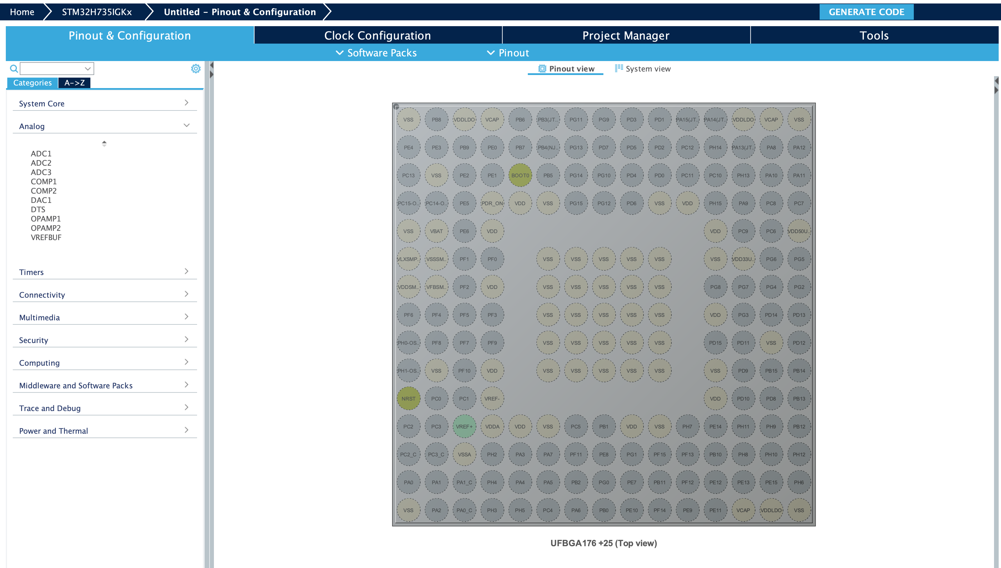
This is our CubeMX menu. We will configure all the parameters using this menu.
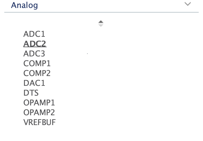
First, we need to enable our ADC. In this microcontroller, we have three ADCs. We will be using ADC1. Click on analog and select your ADC of your choice. Check your datasheet to find the correct ADC and channel that corresponds to your pin.
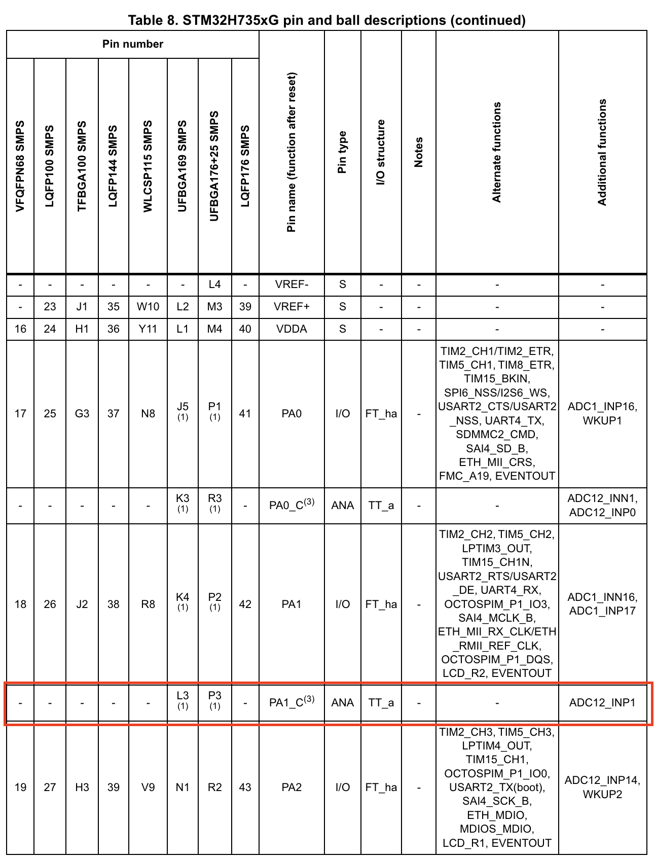
This is the datasheet of the microcontroller. We can see that PA1_C pin is connected to both ADC1 and ADC2 Channel 1. We will select ADC1.
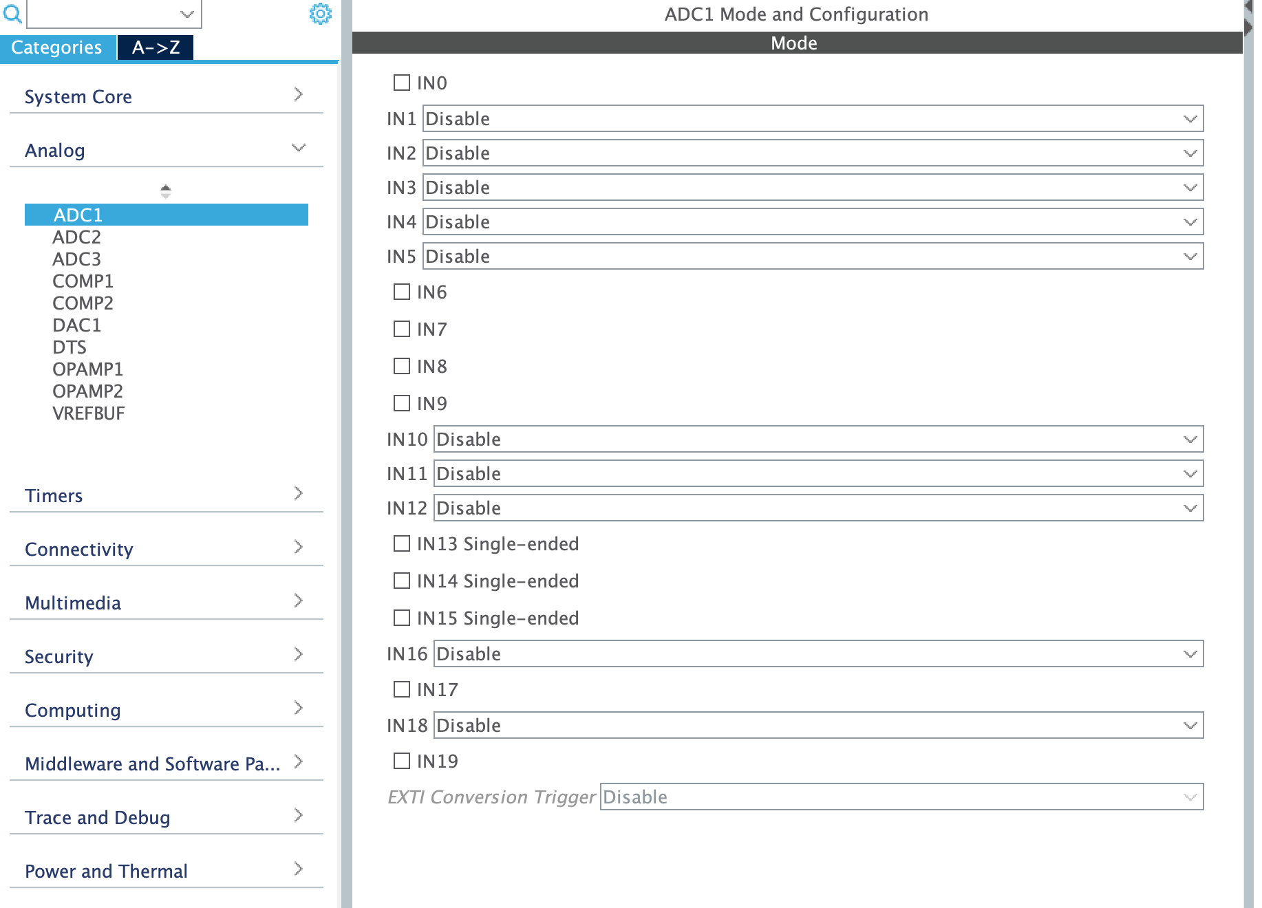
After selecting the ADC, now we need to configure our ADC.
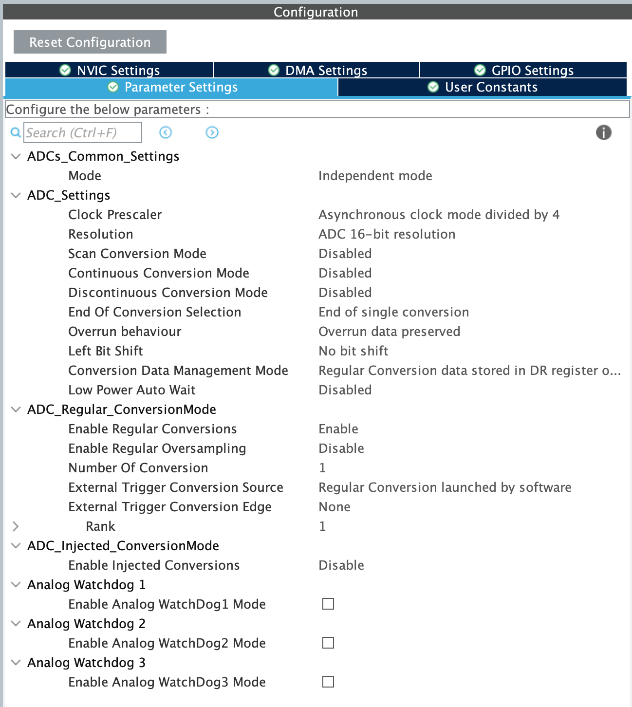
This is our configuration panel. We need to set the parameters according to our use case. This screen will be your best friend (and your worst enemy).
First, I will explain the simplest way you can configure your ADC. After that, I will explain all the parameters in detail.
Simplest way to configure your ADC
The simplest way to use your ADC is to use the default settings. This is not recommended as you will not get the best performance out of your ADC. But if you are in a hurry, this is the way to go. When you select an ADC using the analog menu, the default settings will be applied. Your ADC bit depth will be set to maximum, your sampling time will be set to 1.5 cycles, and your clock source will be set to the maximum, and your conversion mode will be set to single conversion.
With this configuration you can start converting your analog signals to digital signals. Here is an example.
int main(void)
{
  HAL_Init();
  SystemClock_Config();
  MX_GPIO_Init();
  MX_ADC1_Init(); // This function will be generated by CubeMX
  MX_USART1_UART_Init();
  /* USER CODE BEGIN 2 */
  HAL_ADC_Start(&hadc1); // Start the ADC
 /* USER CODE END 2 */
 /* USER CODE BEGIN WHILE */
  while (1)
  {
    HAL_ADC_PollForConversion(&hadc1, 100); // Poll for conversion
    uint32_t adcValue = HAL_ADC_GetValue(&hadc1); // Get the value
    printf("ADC Value: %d\n", adcValue);    // Print the value
    HAL_Delay(1000);    // Wait for 1 second
    /* USER CODE END WHILE */

  }
}
This code will start the ADC and start converting the analog signal to digital signal. The digital signal will be stored in the adcValue variable. This value will be printed to the console every second. This will work for the most basic use of ADCs. If your use case is to check a potentiometer every few seconds, this will suffice.
Detailed explanation of all the parameters: I need more control!
If you need more control over your ADC, you need to configure all the parameters. Here is a detailed explanation of all the parameters.
First, we need to identify the issues with the implementation above. The most critical is that we manually start the ADC and wait for the conversion to finish. This is not the best way to use the ADC. With this method, our CPU will be busy waiting for the conversion to finish. This is not efficient. We need to use the DMA to transfer the data from the ADC to the memory. This way, our CPU can do other tasks while the ADC is converting the signal.
What is DMA?
DMA stands for Direct Memory Access. It is a feature of microcontrollers that allows peripherals to transfer data to and from memory without CPU intervention. This is very useful when you have a lot of data to transfer. In our case, we will use DMA to transfer the data from the ADC to the memory.
When DMA is used, the CPU will not be involved in the data transfer. The CPU will be free to do other tasks. This is very useful when you have a lot of data to transfer. In our case, we will use DMA to transfer the data from the ADC to the memory. DMA will also allow us to use multiple channels and set buffers much easily.
How to use DMA with ADC?
Let's configure the DMA with the ADC. First, we need to enable the DMA in the CubeMX.
Click the DMA Settings menu under your configurations panel.

Click add, and select your ADC.
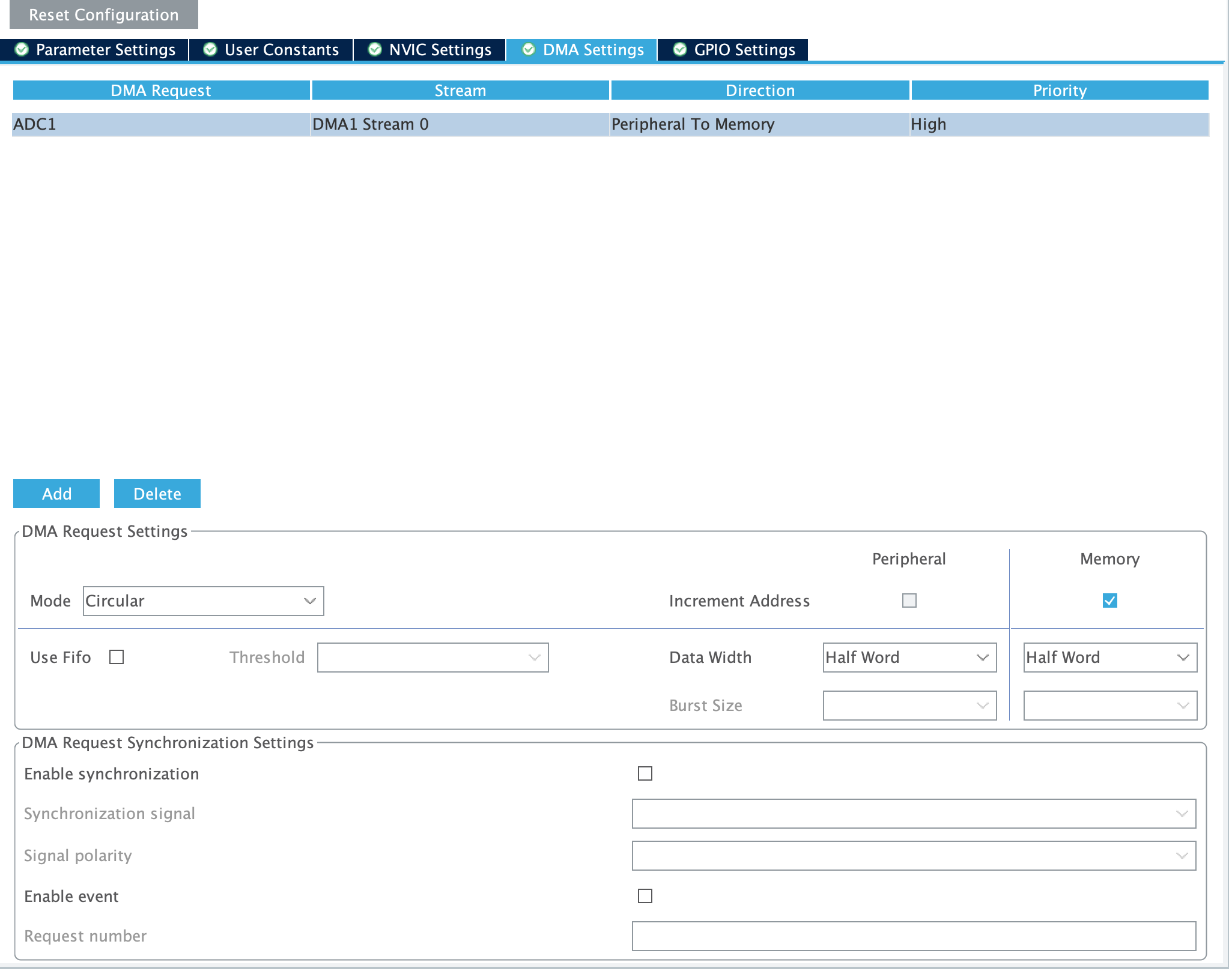
After selecting your ADC, a menu will appear. Select the mode to circular. This will allow the DMA to keep transferring the data from the ADC to the memory. Set the data width to half word. This is the size of the data that will be transferred. Set the priority to high.
Our DMA is ready to use. Now we need to configure the ADC to use the DMA.
Set the conversion data management module to DMA Circular. This will allow the ADC to use the DMA to transfer the data.
Now we need something to manage our conversions.
We have a few ways of doing this. Before going on with the DMA configuration, we need to understand the different modes of the ADC.
ADC Conversion Modes
The ADC in STM32 microcontrollers can operate in different conversion modes. The most common modes are:
- Single mode, which converts only one channel, in single-shot or continuous mode.
- Scan mode, which converts a complete set of pre-defined programmed input channels, in single-shot or continuous mode.
- Discontinuous mode, converts only a single channel at each trigger signal from the list of pre-defined programmed input channels.
Continuous mode is used when you want to continuously convert the signal. Single mode is used when you want to convert the signal only once. Discontinuous mode is used when you want to convert the signal in a specific order.
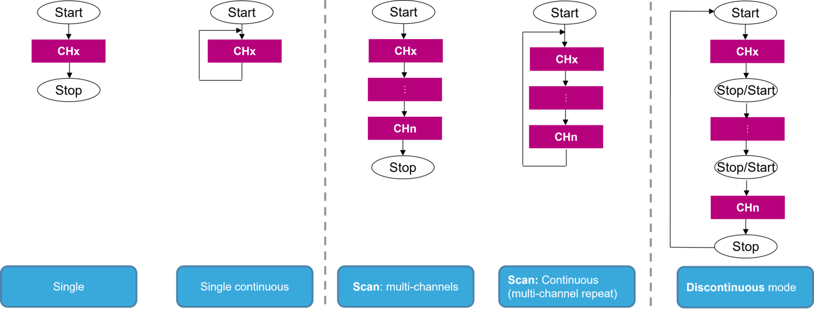
We need a trigger to start the conversion. We can use the continuous mode to automatically trigger the next conversion when the previous one ends. However this is a very imprecise method of using ADCs. Most likely, you will have a sample rate appropriate to your use case. A potentiometer can be checked every few hundred milliseconds. A microphone should be checked every 20 microseconds (48KHz). We can use the timer to trigger the ADC. We can also use the software to trigger the ADC. This way, we can start the ADC whenever we want.
STM32 ADCs offer flexible triggering options, allowing you to initiate conversions based on various events or conditions. This feature is crucial for synchronizing ADC conversions with other system events or for precise timing of measurements. Common triggering options include:
- Software Trigger: Conversions are initiated by software commands.
- Timer Trigger: ADC conversions can be synchronized with timer events.
- External Trigger: Conversions can be triggered by external signals through GPIO pins.
- Analog Watchdog Trigger: ADC conversions can be triggered when the input signal crosses certain thresholds.
The choice of trigger depends on your application requirements. For example, timer-triggered conversions are useful for sampling at regular intervals, while external triggers can be used to synchronize ADC conversions with external events.
In this tutorial, we will be using the timer the. Timers are crucial for precise sampling rates. We can set the timer to trigger the ADC at a specific rate. This way, we can have a precise sample rate.
Open your Timers panel and select an appropriate timer. I will be selecting TIM 2.
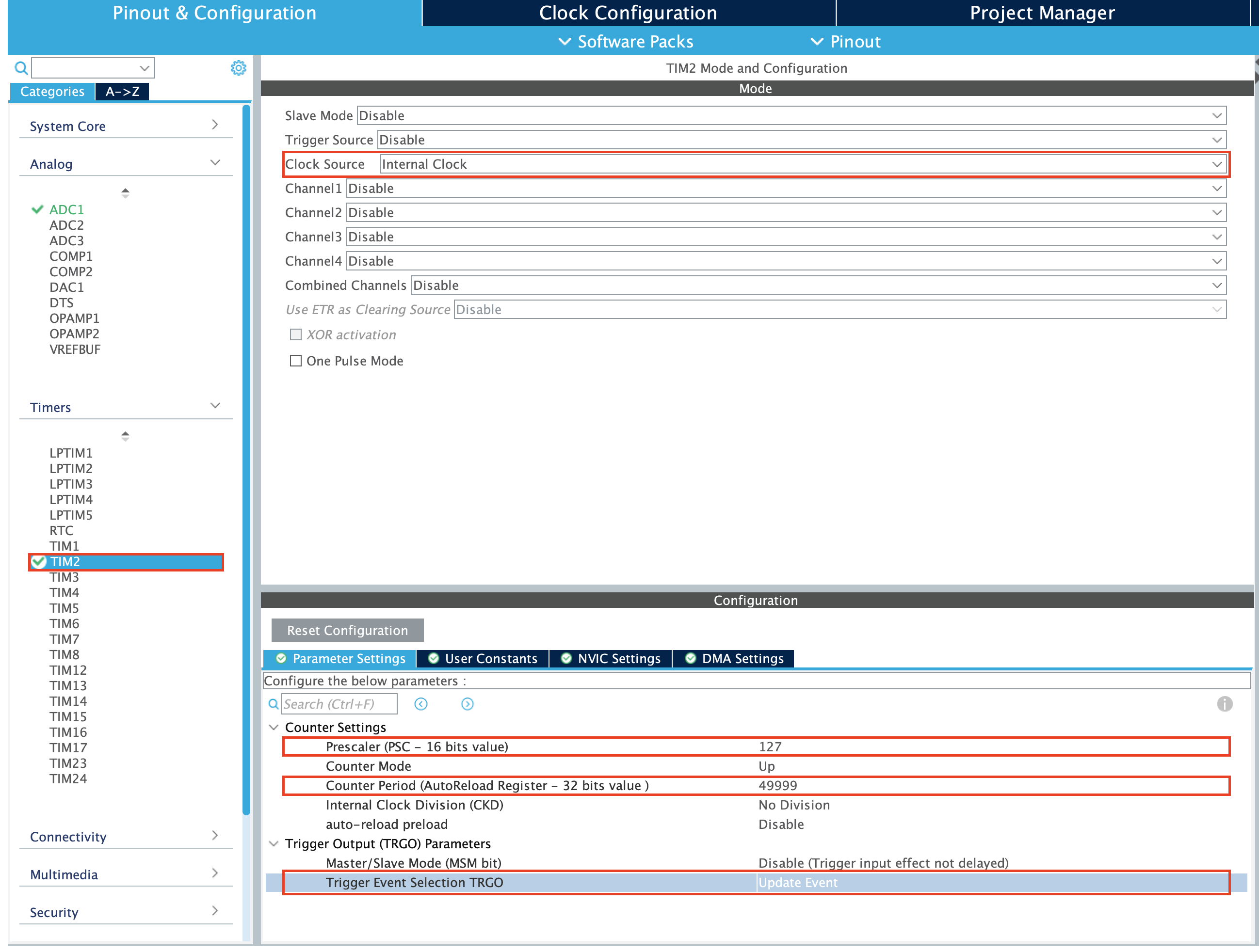
After selecting the timer from the left menu, we need to configure the timer. We need to set the prescaler and the period. The prescaler will divide the clock frequency of the timer. The period will set the frequency of the timer. You can calculate the frequency of the timer using this website: https://deepbluembedded.com/stm32-timer-calculator/
To calculate your timer frequency, you need to know the clock frequency of your timer. Click the clock configuration menu to see the clock frequency of your timer.

The APB1 and APB2 timer clocks are what determines the clock frequency of your timer.
After setting the timer frequency, we need to set the trigger source of the timer. We need to set the trigger source to update event. This will trigger the ADC at the update event of the timer.
I've set the timer to trigger the ADC at 10Hz.
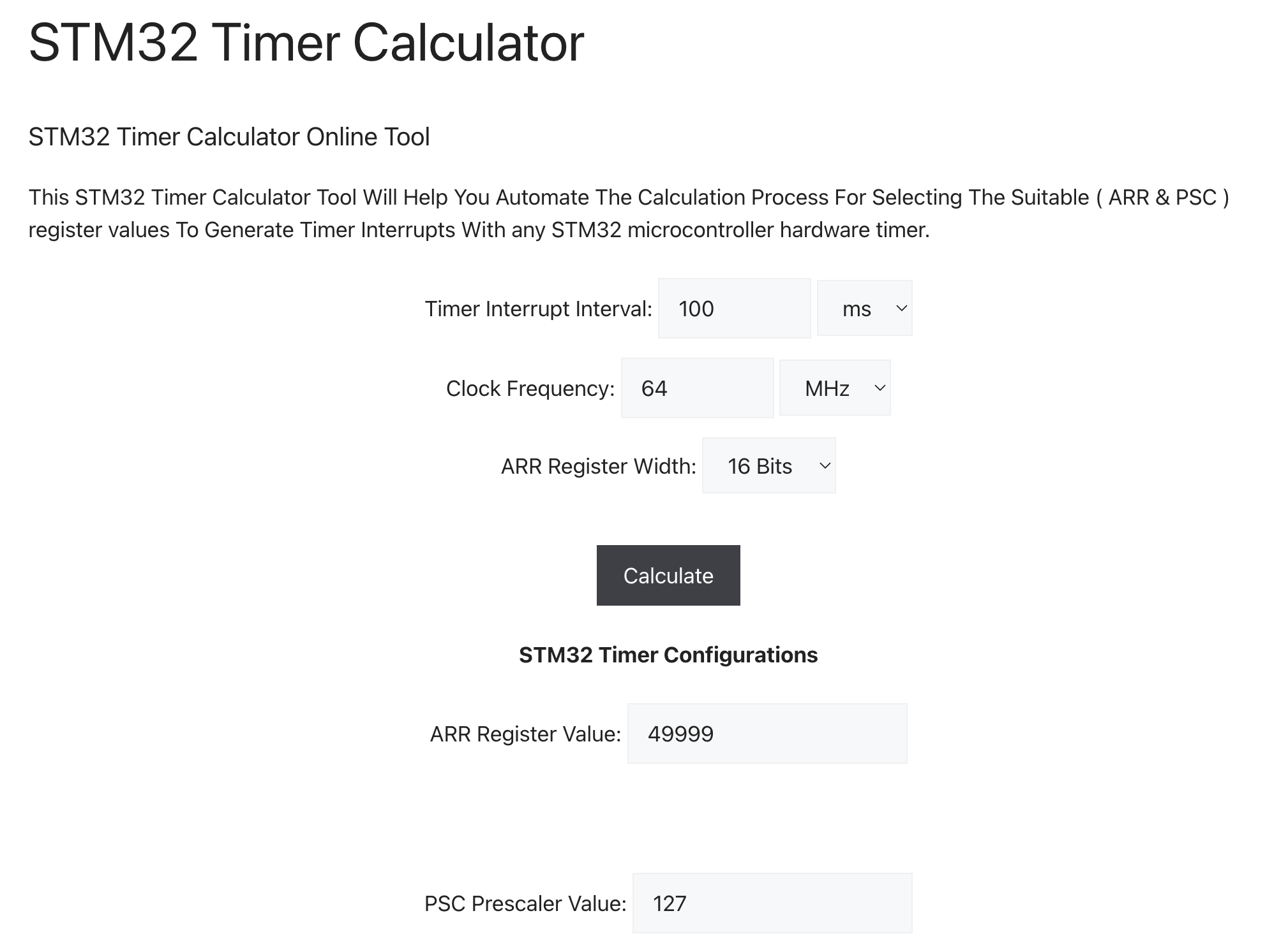
Now we need to set the ADC to trigger at the timer update event.
Set the trigger source to TIM2 trigger out event. This will trigger the ADC at the update event of the timer.
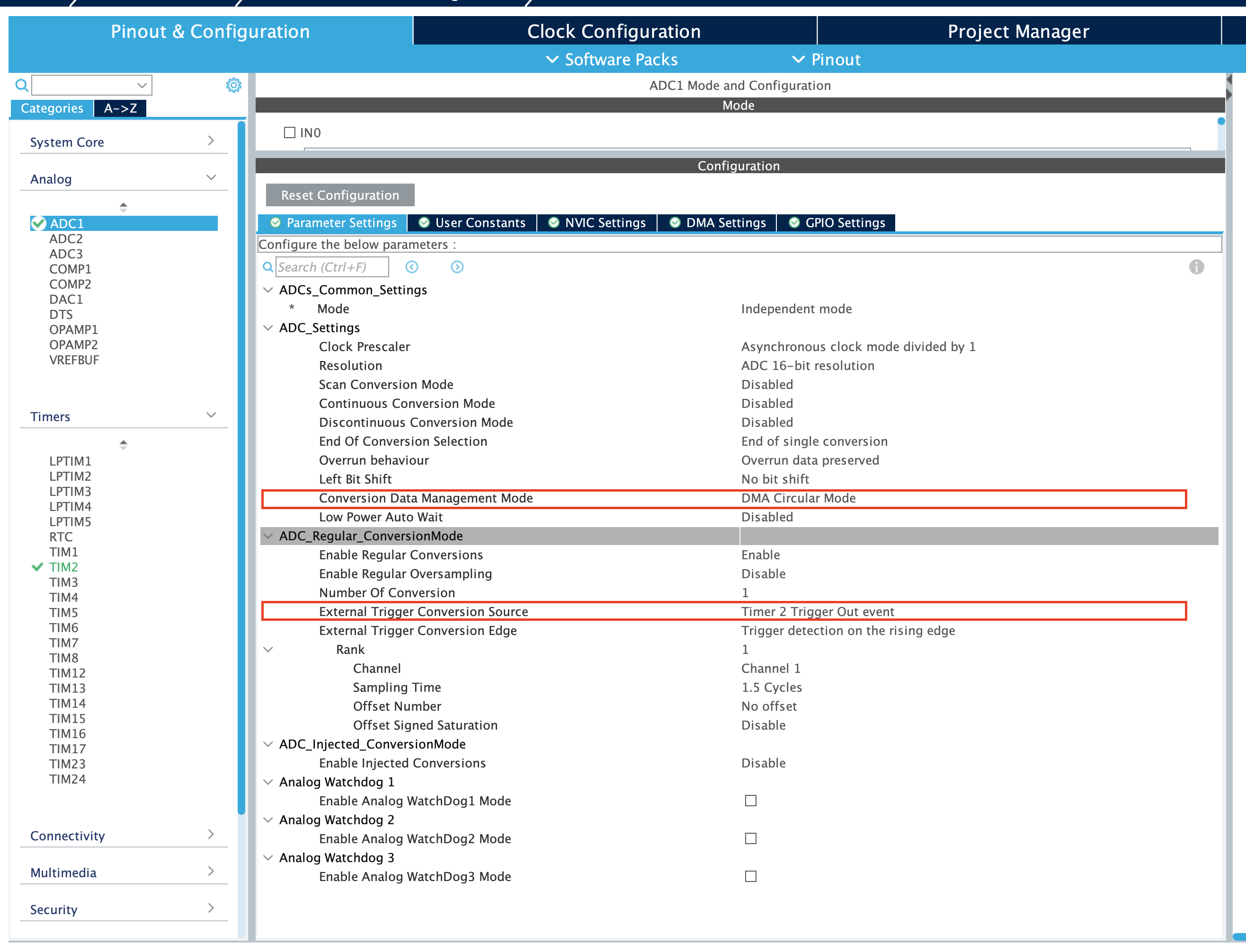
This setup will make us sample our pin every 100 ms. After the ADC value is transferred to the DMA address, we will receive an interrupt. In that interrupt we will be able to access our data.
Here is an example code that will print the ADC value to the console every 100 ms.
uint16_t adcValue = 0
uint16_t DMAValue = 0;
uint8_t ADCCompleteFlag = 0;

int main()
{
    HAL_Init();
    SystemClock_Config();
    MX_GPIO_Init();
    MX_ADC1_Init();
    MX_DMA_Init();
    MX_USART1_UART_Init();
    MX_TIM2_Init();
    HAL_TIM_Base_Start(&htim2); // Start the timer
    HAL_ADC_Start_DMA(&hadc1, (uint32_t*)&DMAValue, 1); // Start the ADC with DMA
    while (1)
    {
        if(ADCCompleteFlag)
        {
        printf("ADC Value: %d\n", adcValue);
        ADCCompleteFlag = 0;
        }
    }
}

/* ... */

/* USER CODE BEGIN 4 */
void HAL_ADC_ConvCpltCallback(ADC_HandleTypeDef* hadc)
{
    adcValue = DMAValue;
    ADCCompleteFlag = 1;
}
/* USER CODE END 4 */
As a rule of thumb, you should do very minimal stuff inside the interrupt. You should set a flag and do the rest of the work in the main loop. The DMA variable should be seperate from the variable that will be used. This is because the interrupt can be called at any time. Your ADC value can change in the middle of your operation.
The code above is what I found to be the safest method of interacting with ADCs.
Multi Channel ADC: I need more data!
If you need to sample multiple channels, you can use the multi channel mode of the ADC. This mode will allow you to sample multiple channels in a single conversion. This is very useful when you need to sample multiple sensors at the same time.
Using DMA is strongly advised as configuring the ADC to sample multiple channels can be very complex without DMA.
To use the multi channel mode, you need to set the number of channels in the CubeMX. You can set the number of channels in the ADC configuration panel.
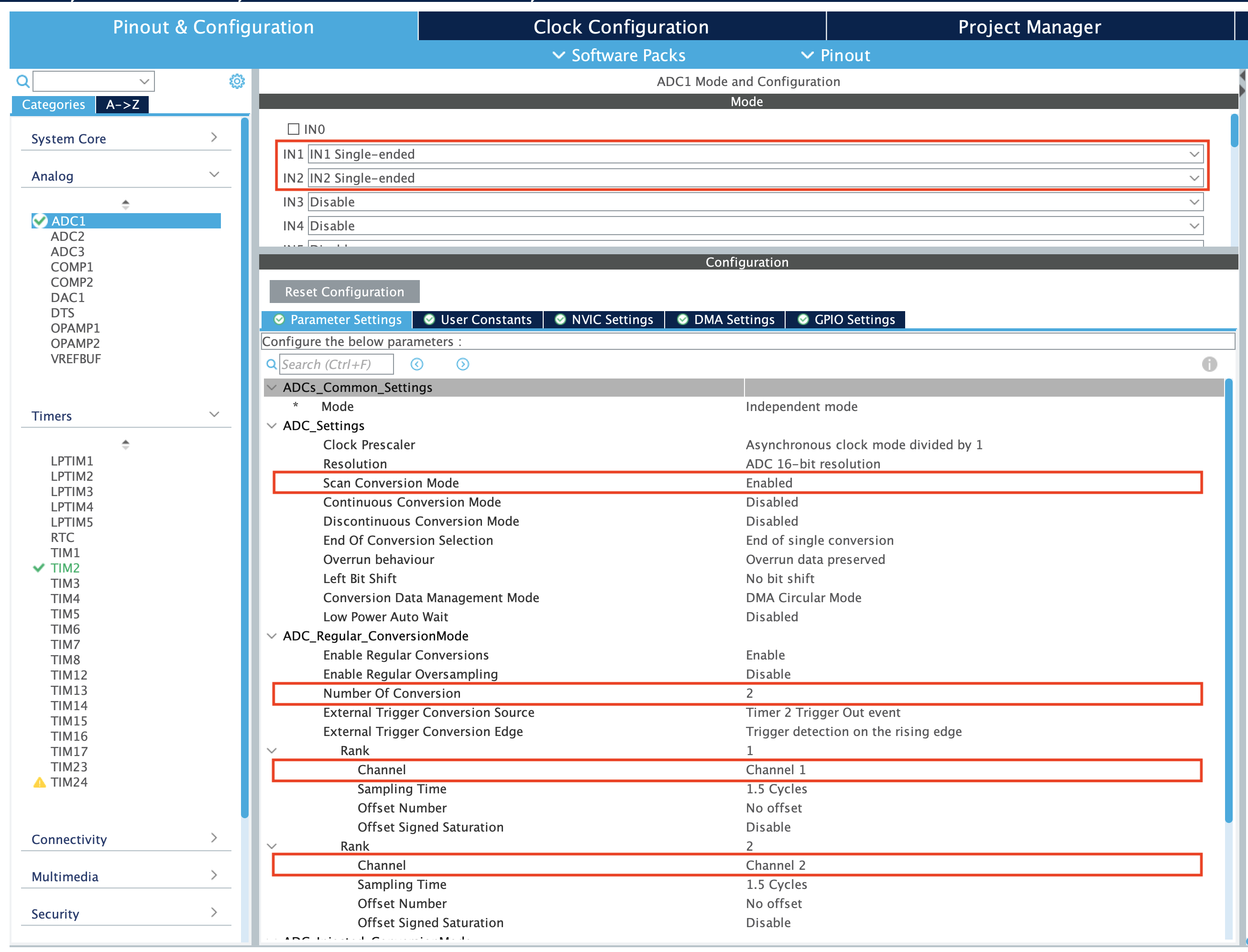
I will sample two channels in this example, IN1 and IN2. Select the inputs you want the use. Set Scan Conversion to enable. This will allow the ADC to scan the channels you selected. Set the number of channels to 2. This will allow the ADC to sample two channels. Under Rank 1 and Rank 2, you will see your ADC channels' configuration panel. Set the channels you want to sample.
Using this method, you can sample multiple channels in a single conversion. This is very useful when you need to sample multiple sensors at the same time.
The ADC will sample the first channel, write to the DMA buffer, and then sample the second channel. This will be repeated until all the channels are sampled.
Here is an example code that will print the ADC values of two channels to the console every 100 ms.
uint16_t adcValue1 = 0;
uint16_t adcValue2 = 0;

uint16_t DMAValue[2] = {0, 0};

uint8_t ADCCompleteFlag = 0;

int main()
{
    HAL_Init();
    SystemClock_Config();
    MX_GPIO_Init();
    MX_ADC1_Init();
    MX_DMA_Init();
    MX_USART1_UART_Init();
    MX_TIM2_Init();
    HAL_TIM_Base_Start(&htim2); // Start the timer
    HAL_ADC_Start_DMA(&hadc1, (uint32_t*)DMAValue, 2); // Start the ADC with DMA
    while (1)
    {
        if(ADCCompleteFlag)
        {
        printf("ADC Value 1: %d\n", adcValue1);
        printf("ADC Value 2: %d\n", adcValue2);
        ADCCompleteFlag = 0;
        }
    }
}

/* ... */

/* USER CODE BEGIN 4 */

void HAL_ADC_ConvCpltCallback(ADC_HandleTypeDef* hadc)
{
    adcValue1 = DMAValue[0];
    adcValue2 = DMAValue[1];
    ADCCompleteFlag = 1;
}

/* USER CODE END 4 */
This code will sample two channels, IN1 and IN2, and print the values to the console every 100 ms.
Accuracy and Precision: How to get the best out of your ADC
The accuracy and precision of the ADC in STM32 microcontrollers depend on various factors, including the ADC resolution, reference voltage, sampling time, and noise levels. To achieve the best performance from the ADC, you need to carefully configure these parameters based on your application requirements.
I strongly recommend ST Microcontrollers' own application note on ADC resolution, AN2834
ADC Resolution
The resolution of the ADC determines the number of discrete levels into which the analog input voltage is quantized. The resolution is typically expressed in bits, with higher resolutions providing more precise measurements. The STM32 microcontrollers support ADC resolutions ranging from 8 to 16 bits, allowing you to choose the appropriate resolution based on your application's requirements.
Sampling Time
The sampling time of the ADC refers to the duration for which the analog input voltage is sampled and held constant by the sample-and-hold circuit. The sampling time is crucial for accurate ADC conversions, as it affects the settling time of the input signal and the accuracy of the conversion process. The STM32 microcontrollers allow you to configure the sampling time based on the input channel and the ADC clock frequency, ensuring optimal performance for your application.
Your ADC sample rate will depend on two durations: the sampling time and the bit conversion time. The sampling time (T_SMPL) is the time the ADC takes to sample the signal. The bit conversion time (T_SAR) is the time the ADC takes to convert the signal to a digital value. The sum of these two durations will give you the sample rate of your ADC.
ADC sample rate = 1 / (Sampling time + bit conversion time) = 1 / conversion time
Your ADC sample time can be configured in the CubeMX ADC configuration panel. The bit conversion time is determined by your bit resolution (12.5 CPU cycles for 12-bit resolution).
You should set the sampling time according to the source impedance of your signal. If your source impedance is high, you should set the sampling time to a higher value. If your source impedance is low, you can set the sampling time to a lower value.
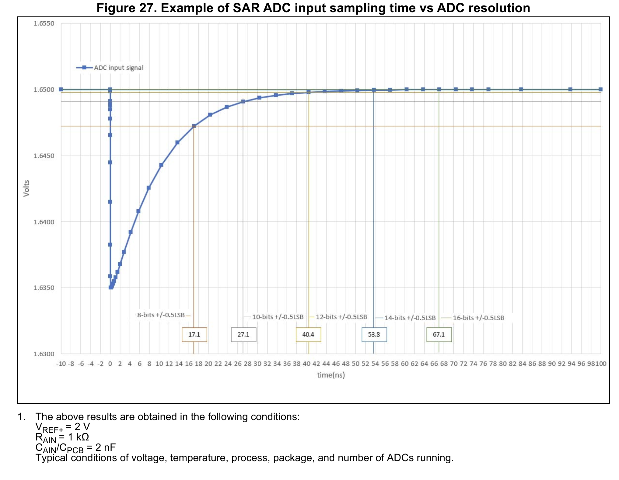
You should take the ADC impedance into account when setting the sampling time. Check your datasheet for R_ADC and C_ADC values. The sampling time should be set according to these values plus your source impedance.
Oversampling: More accuracy, MORE!
Oversampling is a powerful technique available in many STM32 ADCs that can significantly enhance the resolution and reduce noise in your measurements. This feature allows you to achieve higher effective resolution than the ADC's native resolution, which can be particularly useful in applications requiring high precision.
Here's how oversampling works:
- Multiple samples are taken for a single measurement.
- These samples are averaged to produce a final result.
- The averaged result has a higher effective resolution and reduced noise compared to a single sample.
The STM32 ADCs offer hardware oversampling, which means this process is handled automatically by the ADC hardware, reducing the load on the CPU. The oversampling ratio can typically be configured from 2x to 256x, depending on the specific STM32 model.
For example, using 16x oversampling on a 12-bit ADC can provide an effective resolution of 16 bits. This increase in resolution comes at the cost of a lower overall sampling rate, as multiple samples are needed for each measurement.
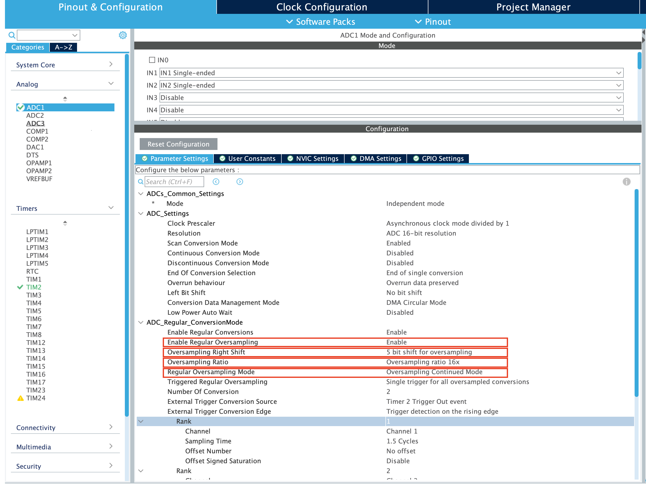
To use oversampling, set Enable Regular Oversampling to Enable. New options will pop out. Oversampling ratio sets the number of samples to be added. To have the same gain as a non-oversampled ADC, you need to set the oversampling ratio to a power of two and bit shift accordingly. For example, 16x oversampling ratio is equivalent to 4 right bit shifts.
Multiple ADCs: One is not enough
If you need more ADCs, you can use multiple ADCs in the STM32 microcontrollers. This is very useful when you need to sample multiple signals at the same time.
To use multiple ADCs, you need to enable the ADCs in the CubeMX. You can enable the ADCs in the analog menu.
After enabling the ADCs, you can configure the ADCs as you would with a single ADC. You can set the resolution, sampling time, and other parameters for each ADC.
ADC Common Modes
The STM32 microcontrollers offer various common modes for multiple ADCs, allowing you to synchronize the operation of multiple ADCs for precise measurements. Common modes include:
- Independent Mode: Each ADC operates independently, with separate control and conversion sequences.
- Dual Regular Simultaneous Mode: Two ADCs perform regular conversions simultaneously, with synchronized start and stop sequences.
- Dual Regular Interleaved Mode: Two ADCs perform regular conversions in an interleaved manner, with alternating conversions between the two ADCs.
For more detail, you should read the application note on ADC modes, AN3116
Digital Analog Converters: The other way around
While ADCs convert analog signals into digital values, Digital-to-Analog Converters (DACs) perform the opposite operation, converting digital values into analog signals. DACs are essential for generating analog output signals in various applications, such as audio processing, motor control, and sensor interfacing.
The STM32 microcontrollers offer built-in DACs that provide high-resolution analog output signals with low noise and distortion. These DACs can be configured to generate precise voltage levels, current outputs, or waveform signals, making them versatile tools for a wide range of applications.
DAC Initialization and Configuration
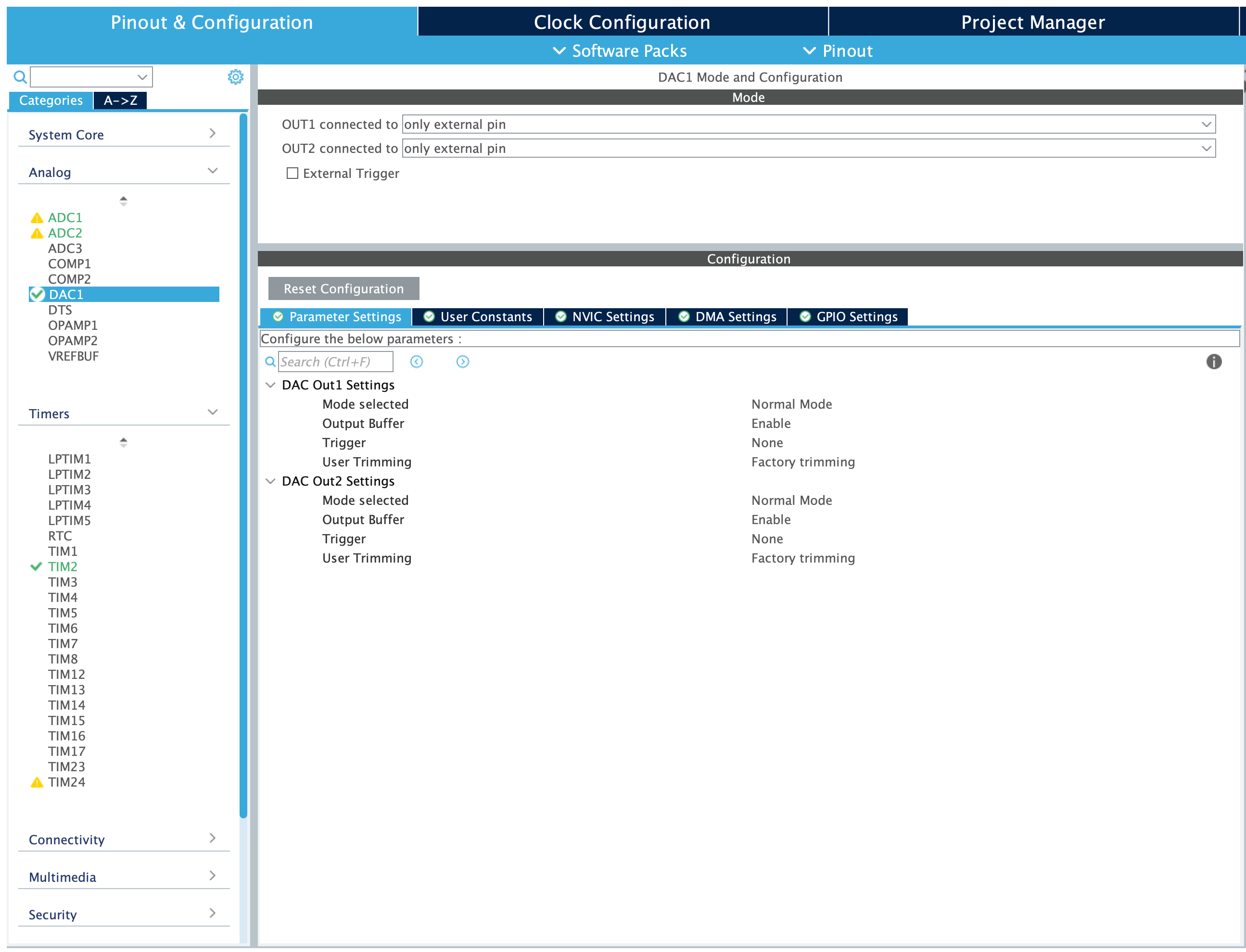
To use the DAC in STM32 microcontrollers, you need to enable the DAC in the CubeMX. You can enable the DAC in the Analog menu.
The default settings are usually sufficient for most applications. But I will go over all the parameters in detail as they are not as complex as the ADC.
DAC Mode: The DAC can operate in two modes: Normal and Sample and Hold. In Normal mode, the output is set by the DAC. In Sample and Hold mode, the DAC charges an internal capacitor, and the output is set by the voltage on the capacitor. This mode is useful on low power applications.
Output Buffer: The DAC output can be connected to an external pin or an internal buffer. The internal buffer provides a low-impedance output, while the external pin allows you to connect the DAC output to external circuits.
Trigger Source: The DAC can be triggered by various sources, such as software commands, timers, or external signals. The trigger source determines when the DAC conversion starts. This is useful when you need to synchronize the DAC operation with other system events. In Triggered mode, the DAC converts the data when a trigger event occurs. This is useful when you need to synchronize the DAC operation with other system events. It is best used with DMA. For example, you can connect the DAC to a speaker, set the DMA address to an audio file, use a timer set to the sample rate to the audio file to trigger the DAC and play the audio file.
User Trimming: The DAC output can be trimmed to adjust the output voltage levels. This is useful for calibrating the DAC output to match the desired voltage levels. Factory trimming is usually sufficient for most applications, but user trimming allows you to fine-tune the output voltage levels if needed.
After configuring the DAC in the CubeMX, you can start using the DAC in your code. The DAC can be used in two ways: Polling and DMA.
In Polling mode, you can set the DAC output value using the HAL_DAC_SetValue() function. In DMA mode, you can use the HAL_DAC_Start_DMA() function to transfer the DAC output values from memory to the DAC output buffer.
HAL_DAC_SetValue(&hdac1, DAC_CHANNEL_1, DAC_ALIGN_12B_R, adcValue);The DAC_CHANNEL_1 is the channel you want to use. The DAC_ALIGN_12B is the alignment of the data. As ST Microcontrollers' DACs are (usually) 12 bits, we need the orientation from which we will read the data. DAC_ALIGN_12B_L will read 12 bits from the left, DAC_ALIGN_12B_R will read 12 bits from the right.
Loopback: Applying everything we learned
Here is an example code that will read ADC, and set the same voltage on the DAC.
    uint16_t adcValue = 0;
    uint16_t DMAValue = 0;
    uint8_t ADCCompleteFlag = 0;

    int main()
    {
        HAL_Init();
        SystemClock_Config();
        MX_GPIO_Init();
        MX_ADC1_Init();
        MX_DMA_Init();
        MX_USART1_UART_Init();
        MX_TIM2_Init();
        MX_DAC1_Init();
        HAL_TIM_Base_Start(&htim2); // Start the timer
        HAL_ADC_Start_DMA(&hadc1, &DMAValue, 1); //
        while (1)
        {
            if(ADCCompleteFlag)
            {
            HAL_DAC_SetValue(&hdac1, DAC_CHANNEL_1, DAC_ALIGN_12B_R, adcValue); // set DAC_ALIGN_12B_R if ADC is 12 bit. Set DAC_ALIGN_12B_L if ADC is 16 bit (this will read the data from the left, losing 4 bits).
            ADCCompleteFlag = 0;
            }
        }

    }

    /* ... */

    /* USER CODE BEGIN 4 */
    void HAL_ADC_ConvCpltCallback(ADC_HandleTypeDef* hadc)
    {
        adcValue = DMAValue;
        ADCCompleteFlag = 1;
    }
    /* USER CODE END 4 */
Conclusion
In this blog post, we've explored the world of STM32 ADCs and DACs, learning about their features, operation, and applications. We've covered the basics of ADCs, including the conversion process, configuration, and programming. We've also delved into advanced topics such as DMA, multi-channel ADCs, and oversampling, providing you with the knowledge and tools to harness the full potential of STM32 ADCs in your projects.
I hope this article has been helpful in understanding the world of STM32 ADCs and DACs.